


Researchers from Mie University, Japan Fine Ceramics Center have published a dissertation titled "Dislocations in (011)-oriented vertical Bridgman β-Ga₂O₃ substrates" in Applied Physics Letters.
Background
β-Ga₂O₃ with an ultra-wide bandgap of 4.5 eV and an ultrahigh theoretical breakdown electric field of 8 MV/cm acts as core candidate semiconductor for high-voltage power devices. Devices with thick low-doped drift layers can realize kV-class breakdown voltage, suitable for power grid converters and automotive power chips. Substrate crystallographic orientation directly dominates the crystalline quality of homoepitaxial films. (100) and (201) substrates easily generate twin defects, while (001) and (010) epilayers form line-shaped pits that require CMP post-treatment and raise manufacturing cost significantly. Recently, (011)-oriented substrates attract intensive attention, as their epilayers are free of groove defects and contain low chlorine contamination, enabling vertical transistors with breakdown voltage over 10 kV. However, existing defect investigations mostly focus on EFG-grown (001) wafers, lacking systematic analysis on dislocation configuration and 3D propagation behavior of vertical Bridgman (011) substrates. Researchers only speculate that (011) plane blocks pit-forming dislocations without distinguishing dislocation diversity induced by different crystal growth routes. The magnitude of lattice misorientation at domain boundaries and the correlation between dislocations and epitaxial leakage current remain unclear, forming a critical research gap limiting the optimization of (011)-based high-power Ga₂O₃ devices.
Abstract
Dislocations in (011)-oriented vertical Bridgman β-Ga₂O₃ substrates grown by the vertical Bridgman method was investigated using x-ray topography (XRT), combined with x-ray reticulography. Transmission XRT reveals dislocations lying on the (001) plane and extending along [010], forming arrays associated with domain boundaries. Dislocations on the (011) plane were also identified but differ from those responsible for line-shaped pits on (001) epilayers. Reflection XRT showed good agreement with transmission XRT and enables classification of dislocation types based on contrast features. Reticulography confirms domain boundaries with misorientation on the order of 10⁻⁵ rad, providing insight into defect formation relevant to epi-growth and device performance.
Highlights
First systematically characterize three-dimensional dislocation distribution inside vertical Bridgman-grown (011) β-Ga₂O₃substrates via transmission and reflection XRT combined with reticulography.
Identify two main dislocation populations: (001)/[010] dislocation arrays coupled with domain boundaries and independent (011) plane dislocations with different propagation characteristics.
Clarify that (011) plane dislocations from VB crystal differ from those responsible for line-shaped pits on (001) epitaxial surfaces grown by EFG, due to distinct crystal growth routes.
Quantitatively confirm domain boundary misorientation magnitude of ~10⁻⁵ rad and reveal mixed twist-tilt lattice distortion feature.
Conclusion
In summary, dislocation behavior in (011)-oriented β-Ga₂O₃ substrates grown by the VB method was investigated using transmission and reflection XRT, complemented by x-ray reticulography. Transmission XRT revealed that most dislocations lie on the (001) plane and extend along [010], forming arrays associated with domain boundaries. Dislocations on the (011) plane extending along [100] were also identified and differ from those responsible for line-shaped pits on (001) epitaxial surfaces. Reflection XRT showed good agreement with transmission XRT and enabled classification of dislocation types based on contrast features. Reticulography confirmed domain boundaries with misorientation on the order of 10⁻⁵ rad, consistent with the dislocation density in the arrays. Furthermore, Burgers-vector analyses revealed that the dominant dislocations are characterized by Burgers vectors parallel to the [010] direction, whereas the more complex DA type-II arrays consist of dislocations possessing different Burgers-vector components.
These results indicate that dislocation behavior in (011) substrates is more complex than previously assumed and may depend on the substrate growth method, highlighting the importance of considering both crystallographic orientation and growth conditions when optimizing substrates for epitaxial growth.
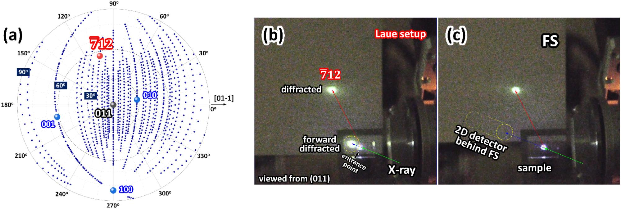
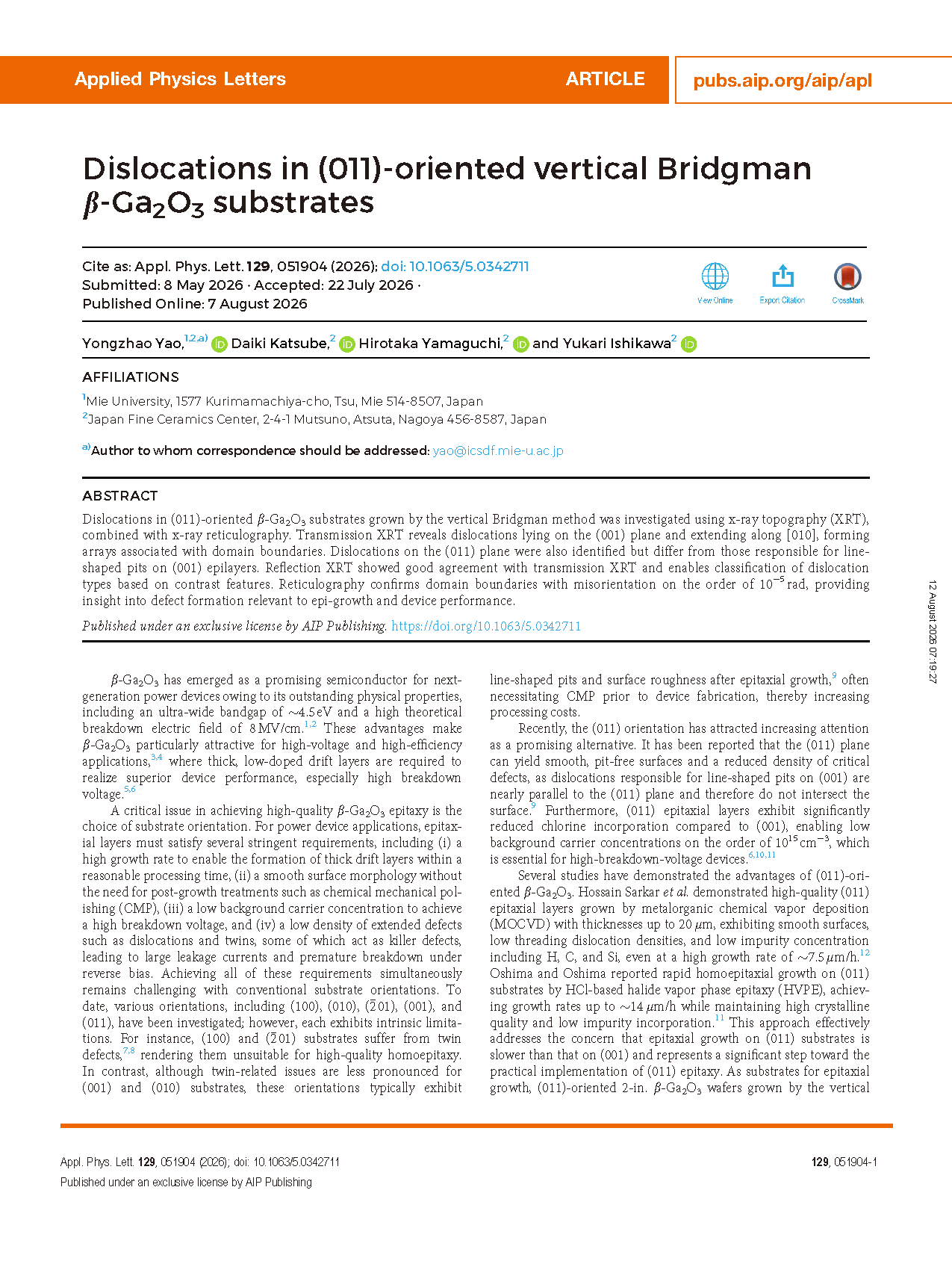
FIG. 1. (a) (011) pole figure of β-Ga₂O₃. (b) and (c) Photograph of the sample and fluorescent screen (FS) under the two-beam Borrmann condition.
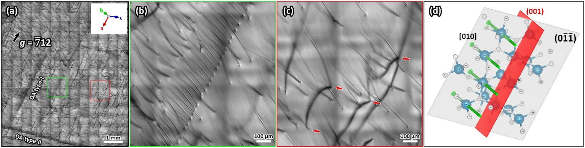
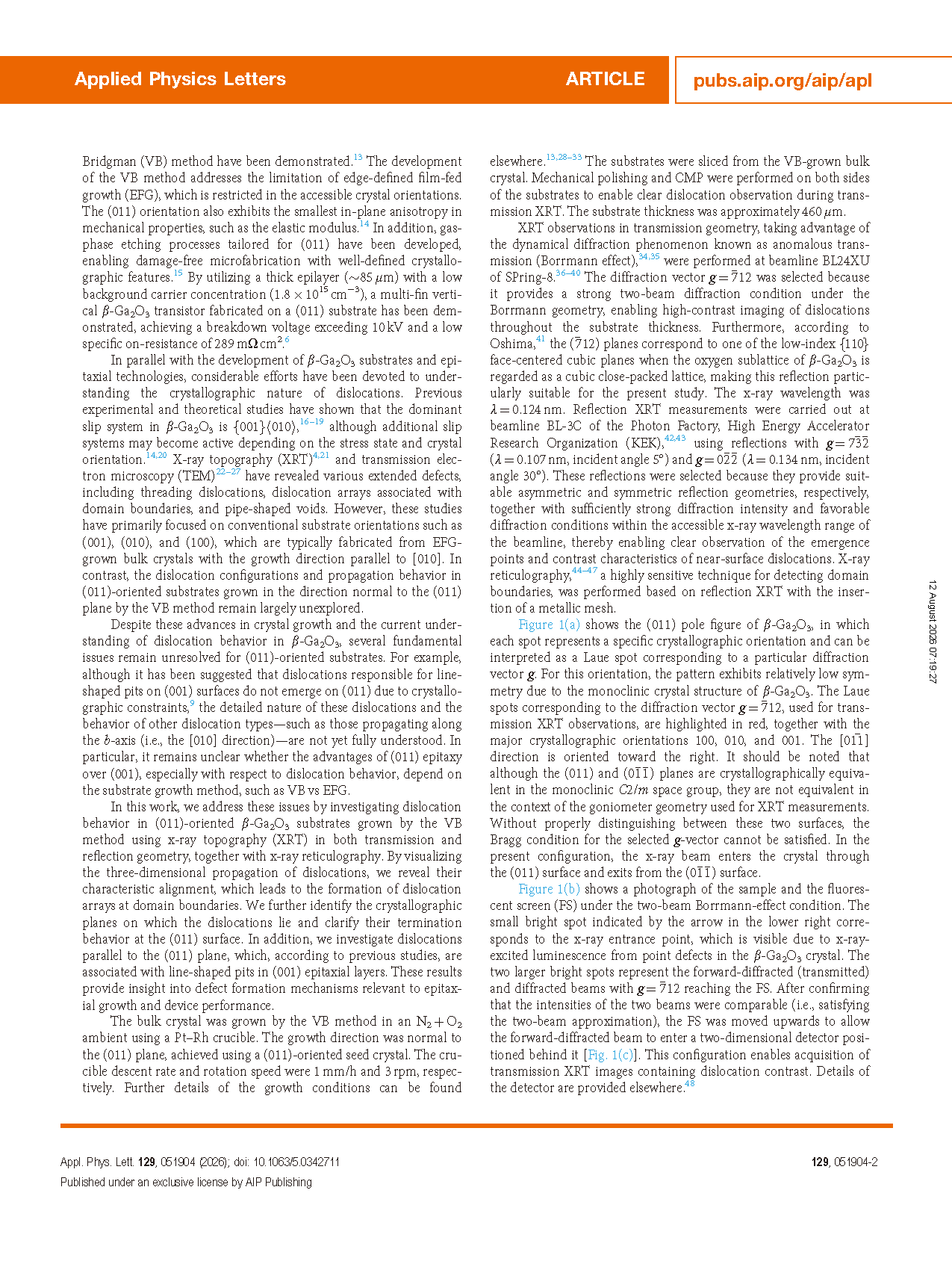
FIG. 2. (a) Transmission XRT image showing isolated dislocations and dislocation arrays. (b) DA type-I array aligned along [100], with dislocations extending along [010] on the (001) plane. (c) Dislocations with uniform thick contrast extending along [100], indicating lines parallel to the surface. (d) Schematic illustration of the crystal geometry. The gray and red planes represent the (0-1-1) and (001) planes, respectively. The green arrows indicate the [010] direction.
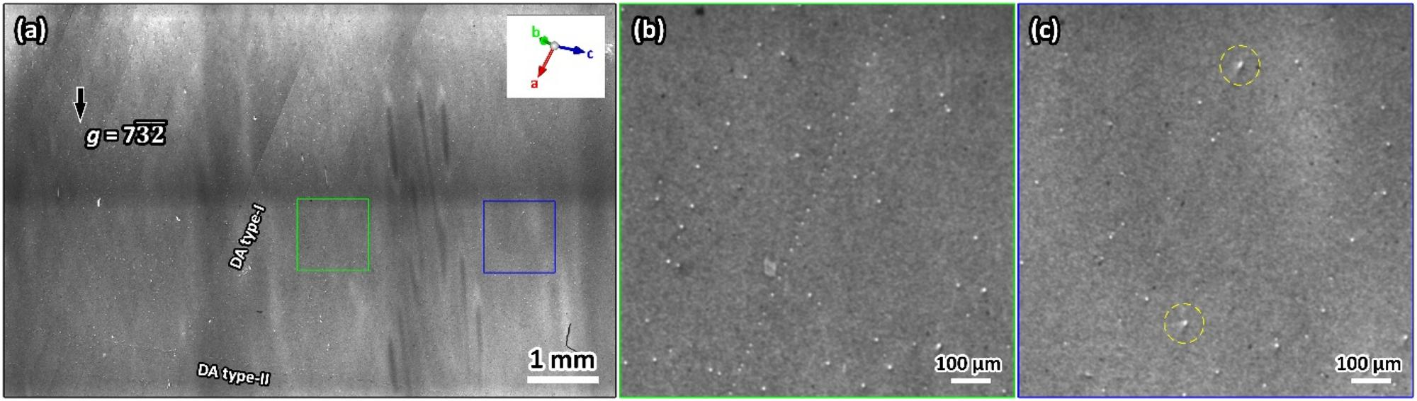
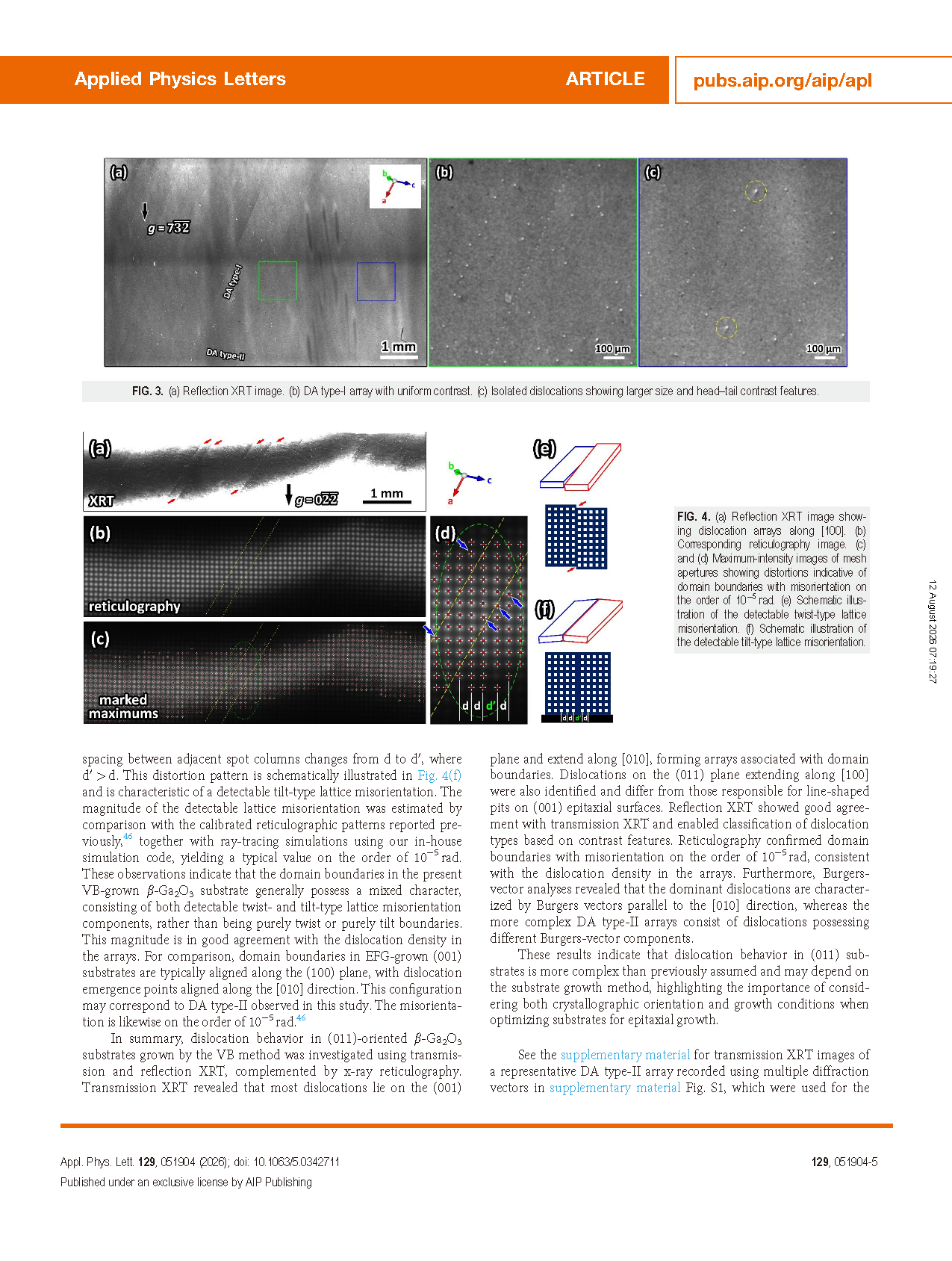
FIG. 3. (a) Reflection XRT image. (b) DA type-I array with uniform contrast. (c) Isolated dislocations showing larger size and head–tail contrast features.
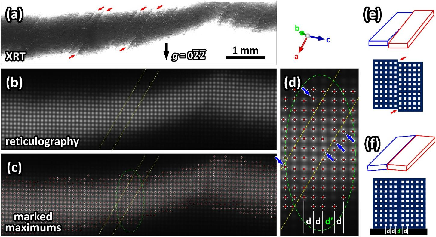
FIG. 4. (a) Reflection XRT image showing dislocation arrays along [100]. (b) Corresponding reticulography image. (c) and (d) Maximum-intensity images of mesh apertures showing distortions indicative of domain boundaries with misorientation on the order of 10⁻⁵ rad. (e) Schematic illustration of the detectable twist-type lattice misorientation. (f) Schematic illustration of the detectable tilt-type lattice misorientation.
DOI:
doi.org/10.1063/5.0342711
Instruction
Official Account

Cooperation
Top